|
WWW.SKUNKWORX.CO.UK |



|
Digital VSWR meter |
|
An ongoing project. The idea behind this is to provide an instrument which is a digital HF VSWR meter, showing forward and reflected power from a transmitter to the antenna. From those values the VSWR is calculated and displayed on the LCD. In addition an alarm will be indicated to show a high VSWR and in some circumstances could be arranged to dump the transmitter power to a dummy load should a high VSWR prevail on unattended equipment. Alternatively this output could provide a logic output to signal remote equipment or inhibit the transmitter during an antenna fault condition.
Latest news: The construction of the project is complete with the code for the PIC working very well.. The whole thing appears to be linear and will work up to a peak value of 200 watts RF. The power displayed works well from 1.8MHz to 72MHz, with a minor fall off of indicated power at 1.8MHz. However the VSWR reading is accurate at these lower frequencies. The alarm circuits work very well in both latching and non-latching modes. The next thing is to verify the circuit in a very rough prototype to ensure the connections between the PIC and the LCD display are correct. The unit works well between 5 watts and 100 watts RF, and as soon as I can cobble together a test circuit I will check the frequency response and linearity up to 200 watts on the HF band and 50 watts on 4m.
The unit has been used almost daily on 80m through to 10m amateur radio bands running digi-modes and performs very well. An alternative design has been designed with an LED bargraph to indicate either RF power or VSWR.
Note: I will shortly be working on a version that has an additional audio output, a sliding tone to assist operators who have sight problems. This will I hope be an additional piece of stripboard added between the PIC and the PCB just for an LED bargraph version. 20.11.2012
|
|
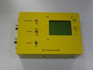
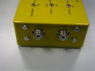
With it’s clothes on. The RF connectors.
|
|
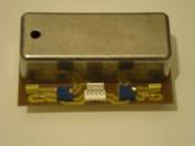
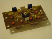
The RF current sensing head used in the VSWR meter. Shown complete on the left with shielding around the major components in this PCB. On the right, the “bits” under the screened can.
If you want to see the “in focus” photos, you will have to buy the magazine. |
