|
WWW.SKUNKWORX.CO.UK |


|
Power supply |
|
This is an interesting project first investigated about sixteen years ago, where I built three versions of the power supply and managed to get the third design published in ETI. This power supply was successful in running at that time a packet radio node from home running three transceivers on 4 metres, 2 metres and 70 centimetres 24 hours a day. Sadly that mode is not currently popular, and has been over taken by the Internet and the faster data connections that provides. Twenty mega bit internet access is just a little faster than 1200 baud packet.
I felt the need to revisit this circuit bringing it up to date and a proposal has been put forward to a British electronics magazine, and it looks hopeful this design will be published in due course. |
|
The design.
The design as in the original is based around a low current dc mains supply, which is able to supply the loads quiescent current for a radio in receive, plus a little extra. This little extra is capable of charging and float charging a gel cell battery which is used as storage. This gel cell battery is able to supply on transmit up to 15 amps at 12 volts. The charging circuit only able to supply some two or three amps at 18 volts. If a constructor is weary about connecting mains voltages to a circuit, then a modular mains power pack can be bought and the low voltage at 18 volts can be attached to the circuit. Thereby removing any high voltage hazards.
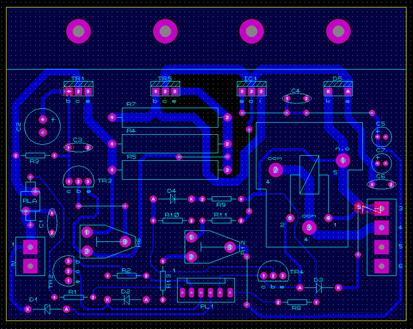
The first PCB layout is shown below: |

|
The circuit is built on one PCB (single sided) and the components are mounted to this board. There is, if needed an indication of power on and high current demand, i.e. greater than 2 amps drawn from the main powered supply and also a fan option should it be needed. Simply power at 18 volts is supplied via the two screw terminals on the left hand side, and the four way terminal on the right hand side connects to the units output at 12 volts and to the storage battery. The six-way connection on the bottom of the board facilitates connection to the LED and the cooling fan.
The final design for publication differs to the design shown here.
The design for publication has been soak testing for about three years with no problems, a good sign. 20.11.2012. |
|
The project has been submitted to EPE and has been accepted for publication, April 2010 edition of EPE. EPE will be supplying PCBs. |