|
WWW.SKUNKWORX.CO.UK |


|
Icom IC718 data interface |


|
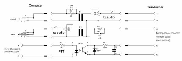
This circuit was designed to interface a computer and an Icom IC 718 HF transceiver. It may be suitable to connect and work with other similar transceivers, check the radios manual before connecting this or any other circuit to the radio. The purpose of this simple circuit is an attempt to provide galvanic isolation the radio from the computer. This goes some way of protecting each device from each other, the computer from high RF voltages and transients that could occur from the radio and antenna installation. Radio interference could be conducted along the leads from the computer to the radio, thus causing additional radio interference.
This circuit has been used successfully with the Ham Radio Deluxe software running PSK- 31 and other digital data modes.
|
|
Consider the transmit audio path; the audio would come from the computers “Line out” port and pass towards the 1:1 isolating transformer Tr1 via R3 and LK1. R3 and LK1 are there to provide some additional attenuation to the audio if required. R5 a preset potentiometer is there to adjust the audio level, this was set to about 70% input to output level from the slider of the preset. The link, LK1 remained in circuit to short out R3. This audio path is fed to the microphone input pin 1 on the 8-pin microphone cable socket. Pin 7 is earth (0v or ground).
The receive signal follows a similar path but in reverse. The received audio from the transceiver is provided at pin 8 of the microphone socket. R6 and LK2 provide a course signal level adjustment. Isolating the signal again with another 1:1 audio transformer, and R2 another 5k preset potentiometer gives a fine adjustment of this audio path. The output is now fed to the “Line in” of the computer.
The PTT is provided from one of the computers serial ports, and the software has to be configured to do so with the option of DTR signalling. Pin 5 being ground, and pin 4 of that serial port providing 5v and sufficient current to turn on the opto-coupler OPTO1. The collector–emitter junction effectively shorts and provides a low resistance path with a 100Ohm resister in series to restrict the current flow.
|
|
The circuit is fabricated on copper clad strip board with all the major components including the audio transformers in place. The connections from the circuit board are brought to connectors on each end of the box, and marked “radio” and “computer”. I used 15 way connectors for this, as they were plenty to be found, and the alternative 9 and 25-way d-types are generally designated for use on serial data and it was best to avoid these as it could cause confusion and disastrous problems with wrong cross connections. |